


pregleda

Proizvedeno u : Aziji
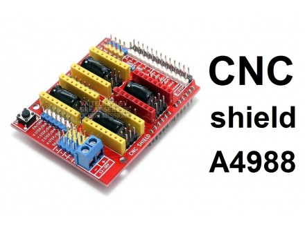
Arduino CNC Shield omogućava da kontrolišete manju CNC mašinu, Laserski engraver ili 3D štampač.
GRBL kompatibilan.
Karakteristike:
- 4 podnožja za step motor drivera A4988
- Napajanje: 12-36 V DC
- Za sve motore postoje jumperi za podešavanje mikrostepinga
- Kontrolni pinovi: Spindle Enable, Spindle direction, Cool enable, Abort, Hold, Resume, E-stop
- Endstop ulazi: X, Y, Z osa
UNO for Arduino module IO port correspondence introduction.
IO corresponding figure above
UNO for Arduino---------------------- expansion board
8 ------------------------ EN ( stepper motor driver enable , active low )
7 ----------------------- Z. DIR (Z -axis direction control )
6 ----------------------- Y. DIR (Y -axis direction control )
5 ----------------------- X. DIR (X -axis direction control )
4 ---------------------- Z. STEP (Z -axis stepper control )
3 ---------------------- Y. STEP (Y -axis stepper control )
2 ---------------------- X. STEP (X -axis stepper control )
/ / The following is a simple stepper motor control procedures,
# define EN 8 / / stepper motor enable , active low
# define X_DIR 5 / / X -axis stepper motor direction control
# define Y_DIR 6 / / y -axis stepper motor direction control
# define Z_DIR 7 / / z axis stepper motor direction control
# define X_STP 2 / / x -axis stepper control
# define Y_STP 3 / / y -axis stepper control
# define Z_STP 4 / / z -axis stepper control
/ *
/ / Function : step . function: to control the direction of the stepper motor , the number of steps .
/ / Parameters : dir direction control , dirPin corresponding stepper motor DIR pin , stepperPin corresponding stepper motor ` step ` pin , Step number of step of no return value.
* /
void step (boolean dir, byte dirPin, byte stepperPin, int steps)
{
digitalWrite (dirPin, dir);
delay (50);
for (int i = 0; i < steps; i + +) {
digitalWrite (stepperPin, HIGH);
delayMicroseconds (800);
digitalWrite (stepperPin, LOW);
delayMicroseconds (800);
}
}
void setup () {/ / The stepper motor used in the IO pin is set to output
pinMode (X_DIR, OUTPUT); pinMode (X_STP, OUTPUT);
pinMode (Y_DIR, OUTPUT); pinMode (Y_STP, OUTPUT);
pinMode (Z_DIR, OUTPUT); pinMode (Z_STP, OUTPUT);
pinMode (EN, OUTPUT);
digitalWrite (EN, LOW);
}
void loop () {
step (false, X_DIR, X_STP, 200); / / X axis motor reverse 1 ring, the 200 step is a circle.
step (false, Y_DIR, Y_STP, 200); / / y axis motor reverse 1 ring, the 200 step is a circle.
step (false, Z_DIR, Z_STP, 200); / / z axis motor reverse 1 ring, the 200 step is a circle.
delay (1000);
step (true, X_DIR, X_STP, 200); / / X axis motor forward 1 laps, the 200 step is a circle.
step (true, Y_DIR, Y_STP, 200); / / y axis motor forward 1 laps, the 200 step is a circle.
step (true, Z_DIR, Z_STP, 200); / / z axis motor forward 1 laps, the 200 step is a circle.
delay (1000);
}
Note: When inserting the A4988 module, must be careful not to insert opposite. Stepper motor wiring as follows:
2A, 2B is a group (red, green), 1A, 1B is a group (blue, yellow), if want to change direction, can be change the position of one group , for example 2A, 2B mutually exchanged.
Predmet: 39802651